


This project involved a customized frame busbar welding system developed for a manufacturer facing higher production demand, unstable weld quality and frequent product changeovers.
HAIFEI combined an MFDC inverter welding power source, a movable welding unit, modular fixtures and PLC control in one dedicated machine. The system was designed for several frame busbar specifications and shortened the welding cycle recorded in this application.
The Equipment Developed for This Project
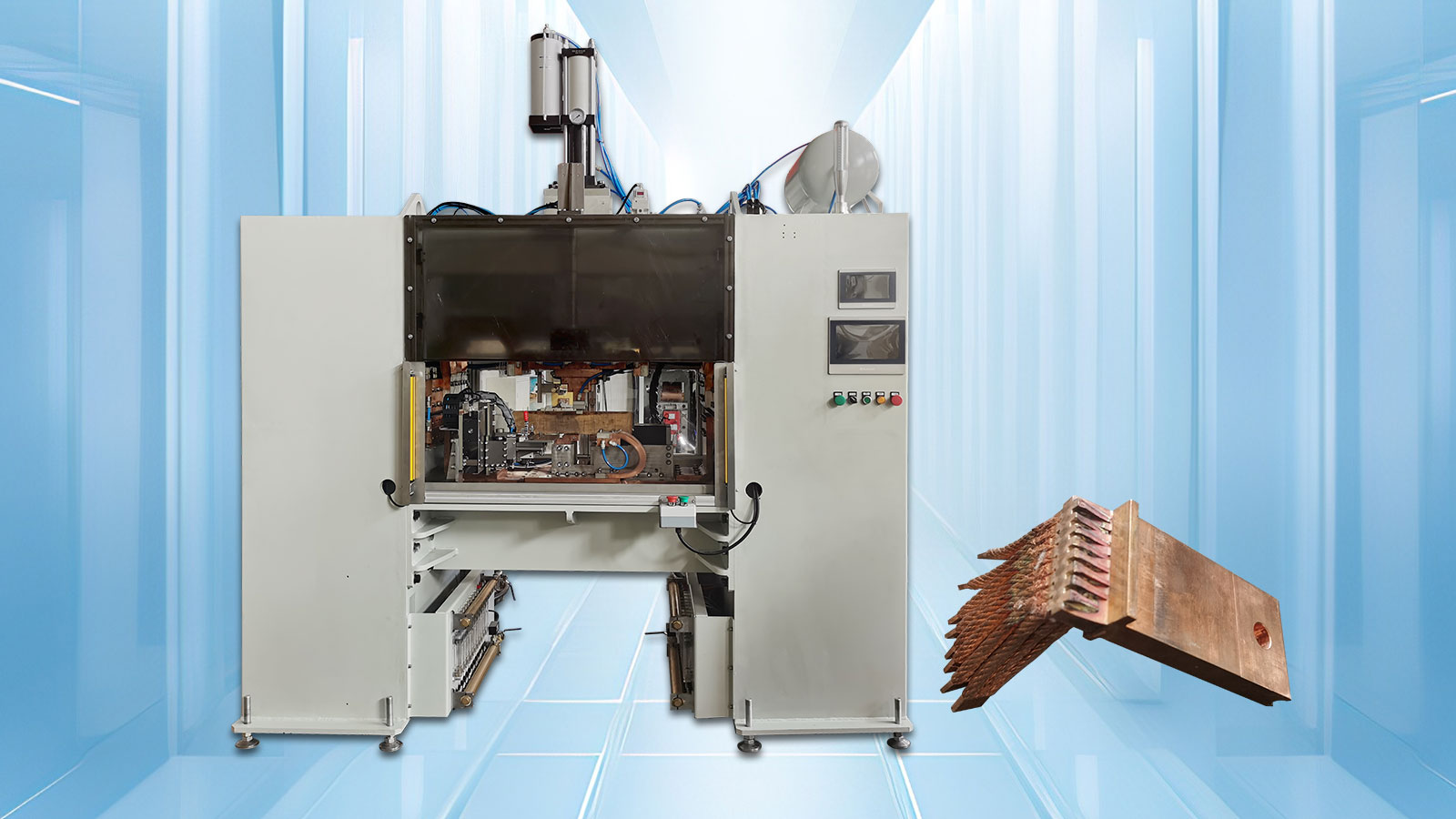
The delivered equipment was a movable MFDC projection welding machine developed specifically for frame busbar assemblies.
Unlike a standard stationary welder, the machine was designed around the size, weld positions and handling requirements of the customer's busbar frame. Its movable welding structure allowed the welding mechanism to reach the required joint positions while the dedicated fixture kept the assembly aligned.
The project configuration included:
- MFDC inverter DC welding power source
- Full-wave rectification and direct-current output
- Movable welding mechanism
- Modular busbar positioning fixtures
- PLC control system
- Human-machine interface
- Stored welding programs
- Safety and operating interlocks
In this delivered system, the power circuit used ABB high-power diodes and Semikron IGBT modules. Components used in future projects should be confirmed in the technical agreement because sourcing and machine requirements may differ.
Project at a Glance
| Project Item | Case Information |
| Customer industry | New-energy electrical equipment manufacturing |
| Workpiece | Frame busbar assembly |
| Equipment | Customized movable busbar welding system |
| Welding process | MFDC inverter DC projection welding |
| Main production issue | Slow cycle and inconsistent welding quality |
| Changeover issue | Existing equipment could not efficiently support different busbar specifications |
| Tooling | Modular, changeable positioning fixtures |
| Controls | PLC and human-machine interface |
| Customer target | A welding cycle of no more than one minute per part |
| Case result | A welding cycle of no more than 45 seconds per part was recorded during acceptance |
The results shown on this page belong to this specific customer project. They should not be treated as guaranteed results for a different busbar design.
Customer Background
The customer manufactures frame busbar assemblies for new-energy electrical equipment. As order volume increased, the existing welding method became a production bottleneck.
The original equipment required approximately three minutes to weld one assembly. It could not provide enough output during periods of high demand. Weld quality also varied, and the existing tooling did not adapt efficiently to different busbar specifications.
The customer therefore needed a dedicated machine that could improve production speed without sacrificing weld consistency or making product changeover more complicated.
Problems That Had to Be Solved
The Existing Welding Cycle Was Too Long
A cycle of approximately three minutes per part limited daily production. Simply increasing the welding current would not solve the problem because part positioning, electrode movement and operator actions also affected the total cycle.
The new system needed to improve the complete operating sequence, not only the welding time.
Weld Quality Varied Between Parts
The original process produced inconsistent weld penetration and assembly quality. The Chinese project record states that the original pass rate was approximately 85%.
For a frame busbar, the fixture, electrode alignment, welding pressure and current delivery must work together. Variations in any of these areas can affect the joint and the final assembly dimensions.
Different Busbar Models Required Repeated Tooling Changes
The customer produced more than one frame busbar specification. The previous equipment had limited compatibility, and frequent fixture replacement increased downtime and operating cost.
The required solution needed a practical way to change between approved busbar models without purchasing a separate machine for each specification.
The Machine Needed to Be Easier to Operate
The customer also wanted a controlled operating sequence that did not depend heavily on individual operator experience. Welding programs, machine status and alarms needed to be visible from a central interface.
What the Customer Required?
The technical objectives for the project were clearly defined:
- Support several approved frame busbar specifications
- Complete one welding cycle within one minute
- Produce even weld penetration without visible cracks or excessive spatter
- Achieve the agreed pass-rate requirement
- Reduce the time required for product changeover
- Provide PLC control and an accessible operating interface
- Simplify operation and parameter selection
- Maintain workpiece position and assembly accuracy during welding
These requirements became the basis for process testing, equipment selection and fixture design.
How WUXI HAIFEI Developed the Solution?
Sample Welding Confirmed the Process
HAIFEI first tested representative workpieces supplied for the project. The engineering team evaluated the frame structure, joint position, welding access and required weld formation.
MFDC inverter DC projection welding was selected after sample testing. Welding current, time, pressure and electrode movement were adjusted around the actual joint rather than taken from a standard machine setting.
This stage also confirmed whether the welding mechanism could reach each weld position without interfering with the busbar frame or fixture.
MFDC Inverter DC Welding Was Used for the Joint
The machine uses three-phase input converted into controlled direct-current welding output. For this project, the process provided the concentrated energy and response required for the frame busbar joint.
The welding program controls the required sequence, including electrode movement, pressurization, current application, holding and release.
Actual settings depend on:
- Busbar material
- Component thickness
- Projection or joint geometry
- Number and location of welds
- Surface coating
- Electrode shape
- Required weld strength
- Final assembly tolerance
These parameters must be developed again when the workpiece structure changes outside the approved range.
A Movable Welding Structure Improved Access
The frame busbar was not treated as a small flat component. Its overall structure and distributed weld positions required a welding mechanism that could move to the required working area.
The customized layout allowed the welding unit to approach the joint while the main assembly remained supported by the fixture. This reduced unnecessary workpiece handling and helped shorten the total operating cycle.
Modular Fixtures Supported Product Changeover
HAIFEI designed a modular fixture system for the approved busbar models.
The fixture established the positioning reference, supported the assembly and kept the welding area aligned with the electrodes. Changeable fixture elements allowed the customer to switch between compatible specifications without replacing the complete machine.
The exact compatible range was defined by the workpiece drawings used during project development.
PLC and HMI Simplified Operation
The control system organized machine movement, clamping, welding and release into a repeatable sequence.
Operators could select an approved program from the human-machine interface rather than manually entering every setting during each production change. The interface also displayed machine status and relevant alarms.
Access to welding parameters can be controlled according to the customer's production-management requirements.
Project Results Recorded During Acceptance
The following figures were reported for this specific frame busbar project.
| Inspection Item | Original Process | Recorded Project Result |
| Welding cycle | Approximately 3 minutes per part | No more than 45 seconds per part |
| Production pass rate | Approximately 85% | At least 99.5% during project verification |
| Assembly verticality deviation | Not stated | No more than 0.05 mm |
| Daily production | Limited by the original cycle | Approximately 650 parts |
| Multi-model production | Frequent and inefficient fixture changes | Modular tooling for approved models |
The equipment also completed a 24-hour continuous trial during factory pre-acceptance. The Chinese project record reports a 99.8% pass rate during that trial.
These figures describe one machine, one group of tested workpieces and the customer's agreed inspection conditions. Results for another project will depend on the busbar structure, material, loading method, number of welds and acceptance standard.
Discuss Your Frame Busbar Welding Project
FAQ
Q: What is a frame busbar welding system?
A: It is a customized welding machine for rigid busbar frames or assembled conductor structures. The system combines a suitable welding power source, workpiece fixture, electrode mechanism and process control around the actual assembly.
Q: What welding process was used in this project?
A: This project used MFDC inverter DC projection welding after sample validation. A different busbar structure may require another welding method, so the process should be confirmed with actual materials.
Q: Why was a movable welding unit used?
A: The frame assembly had distributed weld positions that were difficult to reach with a simple fixed machine. The movable structure allowed the welding mechanism to approach the required joint while the workpiece remained supported.
Q: Can the machine weld different frame busbar models?
A: It can support approved models within the confirmed machine capacity and working range. Different models may require modular fixture components, electrode changes and separate welding programs.
Q: Does every frame busbar require a custom fixture?
A: Usually, yes. The fixture must support the assembly, establish its position and provide access to the weld. Related models may share part of a modular fixture design.
Q: Can copper and aluminum busbars use the same settings?
A: No. Copper and aluminum have different electrical, thermal and surface characteristics. Each material and joint structure requires separate process evaluation and welding parameters.