


Haifei developed this motorcycle steel rim seam welding solution for a manufacturer producing steel rims for motorcycles and electric two-wheelers.
The customer needed more consistent weld penetration, better control of rim deformation and faster changeover between different sizes. Haifei tested steel rims with different diameters and thicknesses before configuring a mid-frequency seam welding machine with controlled heat input, stable roller pressure, closed-loop travel-speed control and reusable welding programs.
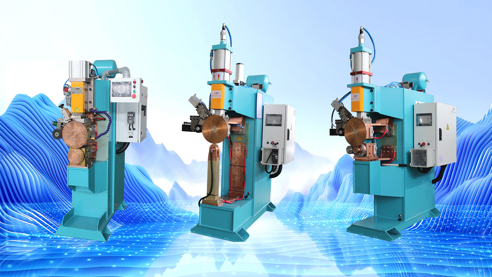
Project Overview
| Project item |
|
| Industry | Motorcycle |
| Workpiece | Formed steel rim |
| Material | High-strength cold-rolled steel |
| Welding area | Circumferential joint on the steel rim |
| Welding process | Mid-frequency resistance seam welding |
| Main concerns | Penetration, joint strength, roundness, runout and weld appearance |
| Product range | Steel rims with different diameters and thicknesses |
| Machine configuration | Customized mid-frequency seam welding machine |
| Process control | Welding current, roller pressure and travel speed |
| Changeover | Replaceable tooling and stored welding programs |
| Verification | Sample trials and customer-defined strength and dimensional checks |
View More Motorcycle Welding Solutions
What Is This Steel Rim Welding Solution Used For?
The solution is used to weld the joint of a formed motorcycle steel rim.
During welding, rotating electrode wheels apply pressure and current while the rim moves through the welding position. The welding current, roller pressure and travel speed must remain coordinated throughout the joint.
The process needs to produce sufficient and consistent penetration without creating excessive heat shrinkage, deep electrode marks or distortion. This is especially important because the finished rim must retain its specified roundness and fit correctly during later wheel assembly.
Although motorcycle and electric two-wheeler steel rims may appear similar, changes in diameter, material thickness and joint structure can require different tooling and welding programs.
What Problems Did the Customer Have?
Uneven Weld Penetration
The customer's previous equipment produced fluctuating heat output. Some areas of the joint received insufficient heat, resulting in incomplete fusion or uneven penetration.
A locally weak joint could become a potential crack-initiation point when the rim was exposed to repeated road impact and torsional loading.
01
Loss of Roundness After Welding
Uneven heat distribution caused different sections of the rim to expand and contract at different rates.
This increased the risk of out-of-round rims and runout deviations, creating additional correction work before wheel assembly.
02
Unstable Roller Pressure
Changes in roller pressure affected the electrical contact and the appearance of the welded joint.
Insufficient pressure could produce unstable current flow and incomplete joining. Excessive or uneven pressure could leave inconsistent electrode indentations or contribute to local deformation.
03
Inconsistent Travel Speed
If the joint moved too quickly through the welding position, the available heat might be insufficient. If it moved too slowly, heat accumulation could increase oxidation, discoloration and distortion.
The previous equipment could not maintain sufficiently stable travel speed during continuous production.
04
Difficult Changeover Between Rim Sizes
The customer produced steel rims in several sizes. Tooling changes and parameter adjustments took time, while previously approved process settings could not be stored and recalled efficiently.
This made production more dependent on operator experience.
05
What Did the Customer Require?
Maintain stable heat input along the complete joint
Produce more consistent weld penetration
Reduce incomplete fusion and local weak sections
Control welding shrinkage and rim deformation
Maintain stable roller pressure and travel speed
Reduce deep indentation, surface burning and discoloration
Support different steel rim diameters and thicknesses
Store welding programs for repeat production
Reduce adjustment time during product changeover
Operate consistently during extended production runs
Final strength, roundness and runout limits were to be confirmed according to the customer's product drawings and acceptance standard.
Why Was Mid-Frequency Seam Welding Selected?
Mid-frequency resistance seam welding allows welding current, electrode pressure and movement to be controlled as one coordinated process.
The rotating electrodes apply pressure to the joint while electrical resistance generates heat at the contact area. As the steel rim moves through the welding position, the weld forms continuously along the required path.
For this application, the main process variables are:
| Process variable | If too low | If too high or unstable |
| Welding current | Incomplete fusion or insufficient penetration | Excessive heat, surface burning or distortion |
| Roller pressure | Poor contact and irregular weld formation | Deep indentation or local deformation |
| Travel speed | Excessive heat accumulation | Insufficient heat and discontinuous penetration |
| Cooling and holding sequence | Joint may move before stabilizing | Longer cycle without additional welding benefit |
| Rim positioning | Weld path may shift from the joint | Uneven pressure and dimensional variation |
These settings must be developed from actual samples. Machine power alone cannot determine whether a steel rim can be welded successfully.
How Did Haifei Develop the Solution?
1. Trials with Different Rim Diameters and Thicknesses
HAIFEI carried out several rounds of welding tests using steel rims with different diameters and material thicknesses.
The trials were used to evaluate:
- Required welding-current range
- Suitable roller pressure
- Travel-speed window
- Penetration consistency
- Electrode indentation
- Visible oxidation and discoloration
- Heat-related deformation
- Rim positioning and support
- Changeover requirements
The test results were then used to define the machine structure, tooling and initial welding programs.
2. Mid-Frequency Welding Power Supply
The selected machine uses a mid-frequency welding power supply to provide controlled current output.
For a continuous rim joint, current stability is important because local fluctuations can change penetration and heat distribution. The power supply allows the welding program to be adjusted according to the rim material, thickness and joint structure.
The final settings are established through sample testing rather than copied from another product.
3. Closed-Loop Travel-Speed Control
HAIFEI configured a closed-loop speed-control system to keep the steel rim moving at the programmed rate.
Stable movement helps maintain a more uniform relationship between welding current and the time each part of the joint remains under the roller electrodes. This reduces variation caused by sudden acceleration or deceleration.
Different travel speeds can be stored for different rim specifications.
4. Controlled Roller Pressure
The roller-pressure system keeps the joint in contact during welding.
Stable pressure supports consistent electrical contact and helps control the depth of the electrode marks. The required pressure depends on material thickness, joint structure, electrode profile and welding current.
Pressure must therefore be developed together with the other process settings.
5. Dedicated Positioning and Supporting Tooling
The tooling locates and supports the steel rim during welding.
Its functions include:
- Keeping the rim aligned with the electrode wheels
- Supporting the circular structure
- Maintaining the welding joint at the required position
- Reducing movement during rotation
- Allowing the operator to load and unload the workpiece safely
- Supporting changeover between agreed rim sizes
For a mixed-model project, replaceable tooling components can be designed according to the diameter range and production schedule.
6. Stored Welding Programs
The control system can store welding settings for different steel rim specifications.
Each approved program may include the corresponding current, pressure, travel speed and welding sequence. When changing products, the operator selects the matching tooling and recipe instead of rebuilding the process from the beginning.
Program storage improves repeatability, but the selected program must still match the loaded rim.
How Did the Solution Address the Original Problems?
| Original problem | Haifei configuration | Intended improvement |
| Fluctuating welding heat | Mid-frequency current control | More consistent heat input |
| Uneven penetration | Coordinated current, pressure and speed | More uniform joint formation |
| Rim distortion and loss of roundness | Controlled heat input and supporting tooling | Reduced uneven thermal shrinkage |
| Inconsistent electrode marks | Stable roller-pressure control | More uniform surface indentation |
| Variable welding speed | Closed-loop travel-speed system | Repeatable movement through the welding position |
| Difficult size changeover | Replaceable tooling and stored recipes | Faster return to approved settings |
| Dependence on operator experience | Programmable welding sequence | Reduced manual parameter adjustment |
| Weak resistance to production interference | Stable control system | More consistent operation during longer runs |
Actual improvement must be confirmed using the customer's agreed inspection and acceptance methods.
How Should the Welded Steel Rim Be Inspected?
A finished weld should not be accepted only by its surface appearance.
The inspection plan should be based on the customer's product standard and may include:
Weld Appearance
Check the joint for inconsistent weld width, excessive indentation, surface burning, cracks or incomplete sections.
01
Penetration and Fusion
Cross-section inspection or another agreed destructive test can be used during process qualification to confirm penetration and joint formation.
02
Roundness and Runout
Measure the welded rim to determine whether heat and pressure have caused unacceptable dimensional deviation.
03
Joint Strength
The test method should reflect the actual service requirements of the steel rim. Depending on the customer's standard, this may include tensile, impact, torsional or fatigue-related testing.
04
Continuous Trial Operation
Before delivery, the machine should be operated with the agreed sample range to check program recall, tooling changeover and process stability.
Inspection method, sampling frequency and acceptance limits must be agreed before final machine acceptance.
05
Why Work with Haifei?
Testing Before Final Configuration
Haifei uses customer drawings and samples to evaluate welding parameters, tooling and machine structure before finalizing the solution.
Equipment and Tooling Developed Together
Steel rim positioning, rotation and support affect both welding quality and dimensional accuracy. The tooling is therefore developed as part of the welding system.
Support for Multiple Product Specifications
Replaceable tooling and stored programs can be planned around the customer's actual product range and changeover frequency.
Pre-Delivery Verification
The equipment can be tested using agreed samples before shipment. The inspection method and acceptance criteria should be confirmed during the technical-review stage.
FAQ

01.Is a motorcycle steel rim the same as a wheel hub?
02.What welding process is used for the steel rim?
03.Can the machine weld different rim diameters?
04.How does the machine help control rim deformation?
05.How is weld strength checked?
06.Can Haifei test our steel rim samples?