

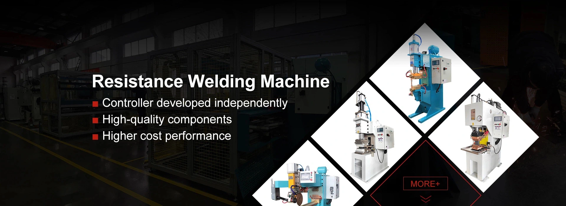
HAIFEI developed a capacitor discharge projection welding machine for joining projection nuts to stainless-steel panels used in electrical cabinets, equipment enclosures and sheet-metal assemblies.
The machine releases stored electrical energy in a short welding cycle. Together with dedicated positioning tooling and controlled electrode force, it helps produce a secure nut joint while limiting panel discoloration, distortion and nut misalignment.

What Machine Was Used for This Project?
The equipment selected for this project was a dedicated capacitor discharge projection welding machine for stainless-steel panels and nuts.
The machine stores electrical energy in capacitors and releases it rapidly through the nut projections. Heat is concentrated at the projection contact points instead of being applied broadly across the panel.
This short energy-release cycle was selected to address three specific production problems: incomplete projection collapse, visible heat marks on the stainless-steel surface and distortion of the panel around the welded nut.
Project Summary
| Project Item | Case Information |
| Customer industry | Low-voltage electrical equipment |
| Workpiece | Stainless-steel panel and projection nut |
| Equipment | Capacitor discharge projection welding machine |
| Welding method | Nut projection welding |
| Positioning method | Dedicated centering and locating fixture |
| Main concerns | Weak joints, panel discoloration, distortion and nut misalignment |
| Product changeover | Tooling and stored parameters for compatible specifications |
| Validation | Sample testing and continuous pre-delivery trials |
Customer Background
The customer manufactures stainless-steel sheet-metal parts, equipment enclosures and related assemblies for low-voltage electrical equipment.
Projection nuts must be welded to the panels before cabinet assembly. The finished nut needs to remain secure during bolt installation, while its thread position must allow the bolt to enter smoothly.
Because the stainless-steel panel is also a visible part of the enclosure, excessive burn marks, yellowing, blackening or deformation can affect both assembly and appearance.
Why Was the Existing Process Unstable?
The original welding process did not consistently concentrate enough energy at the nut projections. Some projections were not fully formed during welding, resulting in weak or incomplete joints.
At the same time, uneven heat distribution created several secondary problems:
| Production Problem | Effect on the Finished Part |
| Insufficient fusion at nut projections | Loose nuts, incomplete joints or weld failure |
| Excessive or uneven heat | Yellowing, blackening and burn marks |
| Uneven thermal contraction | Panel bulging, warping or edge distortion |
| Manual positioning error | Tilted or off-center nuts |
| Unstable energy output | Variation between production cycles |
| Poor nut alignment | Bolt jamming, cross-threading or uneven tightening |
These problems could not be solved only by increasing welding current. More energy could increase surface damage and distortion without correcting nut position or pressure distribution.
What Did the Customer Require?
The customer needed a process that could form the nut projections within a short welding cycle and reduce the amount of heat entering the surrounding panel.
Nut position was equally important. The fixture needed to control centering, perpendicularity and movement during welding so that the thread remained correctly aligned for the following assembly operation.
The equipment also needed to support compatible nut sizes and stainless-steel panel thicknesses. Welding parameters had to be stored for repeat production and future process checks.
The principal requirements were:
- Secure projection welding between the nut and stainless-steel panel
- Less yellowing, blackening and visible surface burning
- Reduced panel bulging and thermal distortion
- Consistent nut position and alignment
- Stable energy delivery between welding cycles
- Easier changeover for compatible product specifications
- Stored welding recipes and process traceability

How HAIFEI Developed the Solution
Welding Trials with the Actual Parts
HAIFEI tested the customer's stainless-steel material and different nut specifications before finalizing the machine.
The trials were used to evaluate projection behavior, welding energy, electrode force, surface condition and panel deformation. Parameters were adjusted according to the actual nut projection geometry rather than using a general setting for every product.
Capacitor Discharge Projection Welding
A capacitor discharge welding system was selected to deliver a large amount of stored energy over a short period.
When pressure is applied, current passes through the nut projections. The electrical resistance at these small contact areas generates localized heat, allowing the projections to collapse and form the joint.
Compared with a longer heating cycle, this process can limit the heat-affected area around the nut. Its suitability still depends on panel thickness, nut material, projection design, surface condition and required joint strength.
Dedicated Centering Fixture
HAIFEI designed positioning tooling for the stainless-steel panel and projection nut.
The fixture locates the part, centers the nut and holds it in position while welding pressure is applied. Uniform support also helps reduce movement and uneven loading during projection collapse.
This tooling was developed to address:
- Nut offset
- Nut tilting
- Movement during electrode contact
- Uneven pressure on the projections
- Inconsistent bolt alignment after welding
Tooling inserts may be changed when compatible nut specifications are produced on the same machine.
Controlled Pressure and Stored Recipes
Welding energy alone does not determine the result. Electrode force, contact condition and timing affect how the nut projections collapse.
The machine therefore coordinates the clamping and energy-release sequence. Approved settings can be stored as product recipes, reducing manual adjustment during repeat production.
Depending on the final equipment configuration, the system can record the selected recipe, weld count, operating status and alarm information. Required data fields and communication interfaces should be confirmed before manufacture.
How Does the Welding Cycle Work?
1
The operator places the stainless-steel panel in the fixture.
2
The projection nut is positioned over the required hole.
3
The fixture centers and supports the components.
4
The welding head applies the preset electrode force.
5
The capacitors release energy through the nut projections.
6
The projections collapse and form the welded connection.
7
The welding head returns and the completed panel is removed.
8
The joint is inspected according to the agreed acceptance standard.
For automated projects, component feeding, part detection and unloading can be added after the basic welding process has been validated.
How Should the Welded Nut Be Inspected?
A nut that looks correctly welded may still be misaligned or mechanically weak. The acceptance plan should cover the joint, thread position and panel condition.
| Inspection Item | What It Checks |
| Visual inspection | Blackening, expulsion, burn marks and surface damage |
| Nut position | Centering, perpendicularity and thread alignment |
| Bolt installation test | Smooth engagement without jamming or cross-threading |
| Push-out test | Resistance to force applied through the panel |
| Torque test | Ability to withstand the specified tightening load |
| Peel or destructive test | Projection formation and joint integrity |
| Panel flatness | Bulging, warping and local deformation |
| Continuous production trial | Repeatability over consecutive welding cycles |
The original case reports stable results during continuous pre-delivery trials but does not publish the numerical acceptance values. Push-out force, torque, flatness and appearance limits should be supplied by the customer or agreed during sample development.
FAQ
Q: What machine is used to weld nuts to stainless-steel panels?
A: This project uses a capacitor discharge projection welding machine. Stored electrical energy is released through the nut projections in a short welding cycle, concentrating heat at the joint area.
Q: Why use capacitor discharge welding for stainless steel?
A: The short discharge time helps limit heat transfer into the surrounding panel. This can reduce discoloration and distortion when the nut projections, welding energy, electrode force and tooling are correctly matched.
Q: Can the process completely prevent panel discoloration?
A: No process should be described as completely eliminating discoloration in every application. Surface results depend on stainless-steel grade, panel thickness, surface condition, projection design and welding settings. Sample testing is required.
Q: Can ordinary nuts be welded with this machine?
A: Projection welding normally requires nuts designed with suitable welding projections. A plain nut without an appropriate projection structure may require a different joint design or process.
Q: Can one machine weld several nut sizes?
A: It may support several compatible nut sizes through replaceable locating parts and stored recipes. The machine capacity, electrode access and tooling space must cover the complete product range.
Q: How do you prevent the nut from tilting?
A: The fixture centers and supports the nut before the welding head applies pressure. The locating structure, electrode alignment and uniform force help control nut perpendicularity during projection collapse.