


HAIFEI developed this ultrasonic wire harness welding machine for joining two tinned copper conductors without solder or filler metal.
The project combines a controlled ultrasonic welding process, dedicated conductor-positioning tooling and stored welding recipes. It was designed to reduce excessive heat input, incomplete conductor bonding, joint stiffness and damage to insulation near the welded area.
Discuss Your Tinned Wire Application
The Equipment Used in This Project
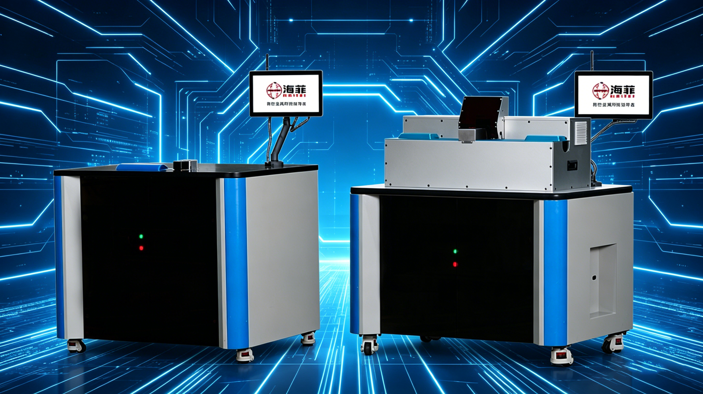
The equipment developed for this application is a dedicated ultrasonic wire harness welding machine.
Ultrasonic metal welding applies high-frequency mechanical vibration while the conductors are held under controlled clamping pressure. The interface between the wires is cleaned and consolidated through mechanical action, creating a solid-state connection below the bulk melting temperature of the conductor.
Because the process does not depend on melting solder, it can reduce the wide heat-affected zone associated with some conventional joining methods. However, the behavior of the tin coating, copper strands and insulation must still be confirmed with the customer's actual wire specification.
| Project Item | Case Information |
| Workpiece | Two tinned copper wire harnesses |
| Welding process | Ultrasonic metal welding |
| Main equipment | Ultrasonic wire harness welding machine |
| Tooling | Dedicated conductor positioning and clamping tooling |
| Primary objectives | Lower heat input, compact joint and stable electrical connection |
| Product compatibility | Multiple compatible wire sizes through verified tooling and recipes |
| Validation method | Sample welding and continuous production trials |
Customer Background
The customer manufactures tinned copper wire harnesses, electrical connecting wires and equipment lead wires for household electrical products and industrial control equipment.
Its products require both electrical continuity and mechanical flexibility. The welded connection must hold the conductor strands together without creating an excessively rigid joint or damaging the insulation close to the welding position.
The customer approached HAIFEI because the previous joining process could not consistently balance heat control, conductor consolidation and production repeatability.
Problems with the Previous Joining Process
Heat Was Affecting the Tin Coating and Copper Strands
A process with excessive localized heat can damage or displace the tin coating, expose the copper underneath and increase the risk of oxidation or discoloration.
High heat can also weaken fine copper strands or create a hardened section around the connection. This reduces the flexibility expected from a wire harness and may affect performance during bending or assembly.
01
The Two Conductors Were Not Always Fully Consolidated
A tinned wire harness consists of multiple fine strands rather than a single solid conductor. If the energy, pressure or positioning is unstable, gaps may remain inside the joint.
Incomplete consolidation can produce weak joints, unstable electrical contact or apparent welds that do not meet the required mechanical performance.
02
Joint Appearance Was Difficult to Control
Oxidation, blackening and process residue were concerns for the customer. These conditions affected appearance and could make it more difficult to judge whether the connection had been produced correctly.
03
Nearby Insulation Could Be Damaged
The welding position is often close to the wire insulation. A wide or uncontrolled heat-affected zone can soften, deform or burn the insulation.
The stripping length, conductor position and distance between the weld and insulation therefore had to be considered as part of the welding process.
04
Product Changeover and Process Records Were Limited
The customer produced more than one wire specification. Manually adjusting the equipment for each model increased setup time and made it difficult to reproduce previously approved parameters.
The new system needed controlled parameter adjustment, stored welding recipes and production data that could be checked when required.
05
What the Customer Needed?
The customer defined several practical requirements for the project:
- Join two tinned copper wire harnesses using a low-heat solid-state process
- Reduce copper strand damage and excessive joint hardening
- Produce a compact connection with fewer internal gaps
- Maintain stable mechanical and electrical performance
- Limit oxidation, blackening and visible residue
- Protect insulation near the welding area
- Support compatible wire sizes through tooling and recipe changes
- Store welding settings for repeat production
- Provide a basis for production and quality traceability
The customer's wire materials, cross-sections and joint arrangement were evaluated before the final machine configuration was selected.
HAIFEI's Ultrasonic Welding Solution
Sample Welding with the Customer's Tinned Wires
HAIFEI carried out welding trials using representative tinned wire samples supplied for the project.
Different welding settings were compared to determine how ultrasonic amplitude, welding energy, pressure and welding time affected conductor consolidation, strand condition and joint appearance.
This testing stage was necessary because tinned wires with different conductor cross-sections, strand structures and coating conditions do not necessarily use the same process window.
Solid-State Ultrasonic Joining
The selected ultrasonic welding process joins the conductors through mechanical vibration and pressure instead of melting solder between the wires.
This helps limit bulk heat input and reduces the risk of the broad thermal damage associated with melting-based processes. The completed connection can retain more of the conductor's original flexibility when the joint design and parameters are properly matched.
Ultrasonic vibration may still disturb or displace part of the tin coating at the welding interface. For this reason, coating condition, exposed copper, corrosion requirements and electrical performance should be inspected during sample validation.
Dedicated Tooling for Two-Wire Positioning
A dedicated welding fixture was designed around the two tinned wire harnesses.
The tooling helps:
- Position the conductors consistently
- Control the overlap or splice area
- Prevent individual strands from spreading
- Support the conductors during clamping
- Maintain the required distance from the insulation
- Improve repeatability between welding cycles
Changeable tooling can be evaluated when several compatible wire sizes must be produced on the same machine.
Controlled Welding Recipes
Approved welding settings can be stored as product recipes. Operators can select the relevant recipe during product changeover instead of rebuilding the complete process setting manually.
Depending on the final configuration, recorded items may include:
- Product or recipe number
- Welding time or energy
- Ultrasonic amplitude
- Clamping or welding pressure
- Weld count
- Alarm information
- Production result
Available recording and communication functions should be confirmed during project specification.
What Was Checked Before Delivery?
The equipment was subjected to pre-delivery testing and continuous production trials using representative workpieces.
The case confirms that production stability was evaluated, but it does not publish numerical cycle-time, pull-force or electrical-resistance results. These values should therefore be defined in the customer's acceptance specification.
Recommended checks for a tinned wire ultrasonic weld include:
| Inspection Item | Purpose |
| Visual inspection | Checks strand escape, cracks, surface damage and discoloration |
| Weld width and thickness | Confirms dimensional consistency |
| Pull-force testing | Evaluates mechanical strength of the splice |
| Electrical resistance | Checks the electrical performance of the connection |
| Cross-section inspection | Examines internal strand consolidation and remaining voids |
| Bend or flex test | Evaluates flexibility near the welded area when required |
| Insulation inspection | Checks for heat, pressure or tooling damage |
| Repeated-cycle trial | Confirms process stability over continuous production |
The test method, sampling frequency and acceptance limits should be agreed before final equipment acceptance.
FAQ
Q: What is tinned wire ultrasonic welding?
A: Tinned wire ultrasonic welding is a solid-state process that uses high-frequency mechanical vibration and pressure to join stranded tinned copper conductors. It does not require solder or filler metal.
Q: Does ultrasonic welding melt the tin coating?
A: The process operates below the bulk melting temperature of the conductor, but ultrasonic vibration can disturb or displace the tin coating at the joint interface. The coating condition and electrical performance should be verified using actual customer samples.
Q: Is solder required for the connection?
A: No. Ultrasonic wire welding forms the joint directly between the conductors without solder, brazing alloy or other filler metal.
Q: Can two different wire sizes be welded together?
A: Potentially, yes. Feasibility depends on the cross-sectional difference, strand structure, joint arrangement and available tooling. Sample welding is required before the combination can be approved.
Q: Can the same machine weld several wire specifications?
A: One machine may support several compatible wire specifications through changeable tooling and stored recipes. The total size range must remain within the capacity of the welding system and sonotrode.
Q: Can this machine weld a tinned wire to a terminal?
A: This case focuses on joining two tinned wire harnesses. Wire-to-terminal welding may also be possible, but it requires a separate review of the terminal material, coating, thickness, joint access and strength requirements.