

In automotive manufacturing, new energy equipment production, sheet metal fabrication, and structural component assembly, the spot welding machine has become a core piece of industrial equipment. Compared with traditional AC systems, modern medium-frequency systems offer more stable current output, better energy efficiency, and higher process control accuracy. As a result, the medium frequency DC spot welding machine is now widely adopted across high-end manufacturing sectors.
However, despite these technological advantages, premature electrode wear remains a persistent operational challenge. Excessive electrode consumption leads to unstable weld quality, higher maintenance frequency, increased downtime, and rising production costs. More importantly, electrode degradation often becomes an "invisible root cause" of weld defects, forcing production teams into repeated cycles of parameter adjustment, electrode replacement, and rework.

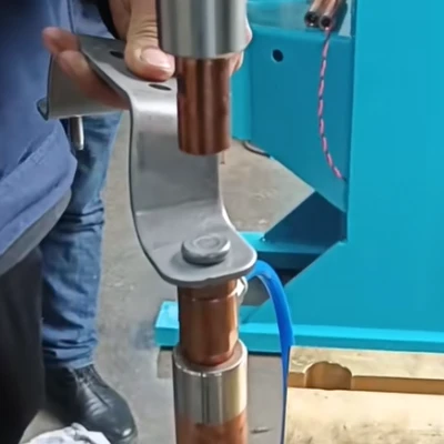


From an engineering perspective, electrode wear is not a simple consumable issue. It is the result of system-level interactions between process parameters, electrode materials, cooling efficiency, workpiece conditions, and machine structure design. Without addressing these factors holistically, replacement alone only treats symptoms, not the cause.
This article provides a structured, engineering-based analysis of electrode wear mechanisms and offers practical, implementable solutions to support better decisions in equipment selection, process optimization, maintenance strategy, and production system design.
Current–Pressure Imbalance: The Primary Source of Thermal Overload
1. Excessive Current and Thermal Softening of Electrodes
When welding current is set too high, intense Joule heating occurs at the electrode tip within milliseconds. Local temperatures rise rapidly, causing thermal softening of copper-based materials and structural deformation. Over time, this leads to characteristic "mushrooming" of the electrode tip, which creates several process risks:
- Expansion of contact area and reduction of effective current density
- Degradation of weld nugget consistency
- Increasing instability in weld quality
- Accelerated mechanical fatigue and material wear
Typical industry reference ranges:
- Low-carbon steel: 8–12 kA/mm²
- Galvanized steel: 10–14 kA/mm²
- Aluminum alloys: higher current density required, with stricter cooling and material demands
2. Insufficient Pressure and Localized Resistance Heating
When electrode force is insufficient or unstable, the contact interface becomes inconsistent, increasing electrical resistance. Heat generation shifts away from the workpiece interface and concentrates at the electrode tip, producing:
- Localized electrode overheating
- Pitting and surface erosion
- Severe sticking and spatter adhesion
- Rapid structural degradation of the electrode
Practical Engineering Solutions:
- Parameter coordination: Welding current, electrode force, and weld time must be adjusted as a unified system rather than independently
- Force control reference: For most steel applications, a pressure range of 0.2–0.4 MPa supports stable nugget formation and controlled heat distribution
- Process strategy selection:
Hard schedule: high current + short weld time (thick plates, high-strength steels)
Soft schedule: lower current + longer weld time (galvanized steel, coated materials)
- System advantage utilization: Modern systems, especially in a MFDC spot welding machine for automotive manufacturing, provide fast current response and stable waveforms that reduce thermal shock and electrode stress
Incorrect Electrode Material Selection: A Structural Mismatch Problem
Performance Characteristics of Common Electrode Materials
| Material Type | Conductivity | Wear Resistance | Typical Applications |
| Chromium zirconium copper (CrZr) | High | Medium | Carbon steel, stainless steel |
| Alumina copper (Al₂O₃-Cu) | Medium-high | High (3–5× CrZr) | Galvanized steel, aluminum |
| Tungsten copper (WCu) | Medium | Very high | Copper and high-conductivity materials |
| Molybdenum alloys | Medium | Very high | High-temperature, high-load applications |
Common Industrial Misconception
Many production lines use a single CrZr electrode type for all applications. When welding galvanized steel, aluminum, or copper materials, this results in severe sticking, abnormal wear, and short electrode life. This is not a quality defect but a material-property mismatch between electrode composition and welding conditions.
Optimization Strategy:
1.Material matching principle:
- Galvanized steel → alumina copper
- Aluminum → alumina copper
- Copper and copper alloys → tungsten copper or molybdenum alloys
2.Composite electrode structures:
Use insert-type designs (e.g., tungsten copper tip + CrZr body) to balance conductivity and wear resistance
3.Procurement logic upgrade:
Electrodes should not be treated as generic consumables; classification by material system and process type significantly reduces long-term operating cost
Cooling System Management: The Hidden Accelerator of Wear
System-Level Impact of Cooling Failure
Insufficient water flow, elevated coolant temperature, or internal channel blockage prevents efficient heat removal, causing long-term high-temperature operation and resulting in:
- Material softening
- Mechanical strength loss
- Local hotspot formation
- Structural fatigue acceleration
- Exponential increase in wear rate
Engineering Control Measures:
- Flow rate standard: ≥ 4–6 L/min per electrode
- Temperature control: Inlet water temperature ≤ 25°C for stable heat exchange
- Water quality management: Use deionized water or industrial coolant to prevent scale buildup
- Structural optimization:
1.Short electrode overhang
2.Enlarged internal cooling channels
3.Reduced flow path bending to avoid hydraulic dead zones
Workpiece Surface Condition: The Wear Multiplier Effect
Mechanism of Influence
Oil, oxides, dust, and surface contaminants increase contact resistance and shift heat concentration toward the electrode, creating a chain reaction:
- Electrode overheating
- Increased sticking probability
- Spatter adhesion
- Surface geometry distortion
- Progressive welding instability
Process Control System:
- Pre-weld treatment: Degreasing, ultrasonic cleaning, pickling for coated materials
- Post-weld maintenance: Standardized electrode dressing and reshaping cycles
- Management principle: Electrode maintenance must be treated as process control, not simple mechanical repair
Equipment Selection Perspective: Reducing Wear at the System Level
Structural Features of High-Quality Systems
A well-designed industrial spot welding machine typically includes:
- Closed-loop current control systems
- High-precision force control (servo systems outperform pneumatic systems)
- Optimized cooling circuit architecture
- High structural rigidity and electrode alignment accuracy
This is particularly important when selecting a servo-driven spot welding machine, where force precision directly affects thermal distribution and electrode lifespan.
Selection Logic:
- Prioritize current stability over nominal power rating
- Evaluate force control accuracy and repeatability
- Assess cooling structure design, not just connection ports
- Include electrode life management capability as a core selection criterion
Conclusion
Electrode wear is not caused by a single factor. It is the combined outcome of process parameters, material matching, cooling performance, surface conditions, and equipment design. Sustainable control requires a system-level strategy:
- Proper material matching
- Scientifically defined parameters
- Structurally reliable equipment
- Stable cooling systems
- Standardized process management
For manufacturers selecting or upgrading a spot welding machine, electrode life management capability should be evaluated with the same importance as welding capacity, energy efficiency, and automation level. Only through system-level optimization can production lines achieve long-term stability, cost control, and consistent weld quality.


